Aurora Visio Studio TOP » Program Examples » Fiducial Markers
Fiducial Markers
目的
The goal of this task is to detect fiducial markers (in the shape of a plus sign) on different images. The markers have the same size, can be rotated, and can both be bright and dark.
Input
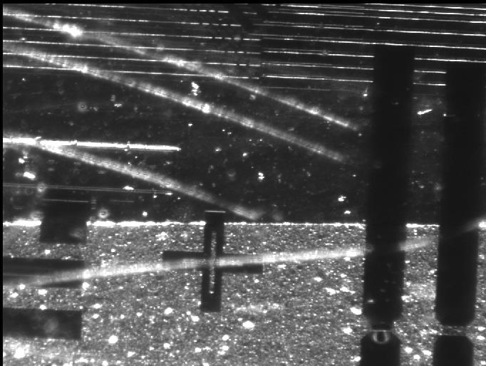
An image of a fragment of an electronic board.
Output
An image with the detected marker marked.

ヒント
The colors of neither the object to detect nor the background are constant. However, between the markers and the background there is always a visible boundary, an edge.
Since none of the input images have a clear view of the marker it may be useful to prepare an artificial image where is is easily noticeable.
接続のラベル付けについては こちらを参照ください。
Solution (AVS)
- In Workspace Explorer open workspace Examples and in Film strip window select FiducialMarker dataset. Drag the Image channel to the ACQUIRE section.
-
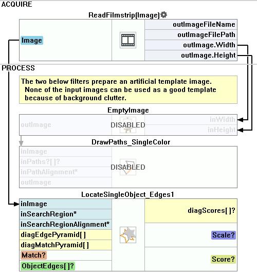
Since it would be difficult to create and edge model from one of the input images due to them being cluttered we should create a training image. To do this start with adding the EmptyImage filter.
- In the ReadFilmstrip filter right click on the outImage, go to property outputs and check both Height and Width .
- Connect the new outputs to the appropriate inputs in the EmptyImage.
- Run the program once to calculate values of outputs.
-
Add the DrawPaths_SingleColor filter. Connect the output of the EmptyImage to the appropriate input
- Now open the path editor by clicking the "..." icon in the inPaths field.
- In the editor you can choose a reference image from the input set.
- Now draw a closed path in the shape of the marker using a real image as reference. Close the editor.
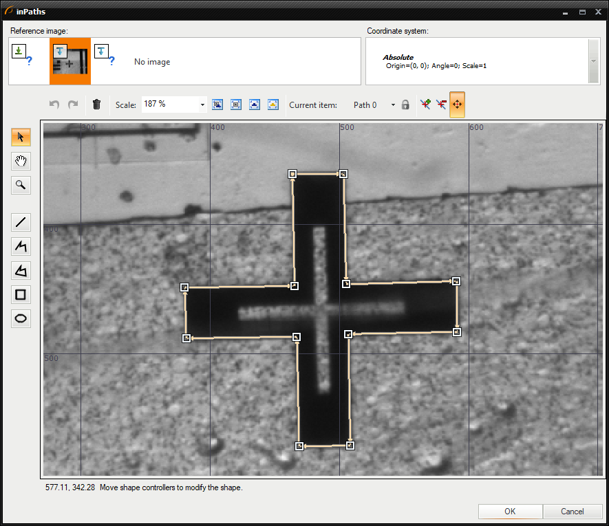
- In the filter properties change the inColor to white.
- Set the Filled parameter of the inDrawingStyle to True.
- Run the program once. Now you should have a black image with a white marker.

-
Now the proper part of detection can begin. Add the LocateSingleObject_Edges1 filter. Open the edge editor by clicking the "..." icon in the inEdgeModel field.
- Mark the area of the marker and set the parameters like it is shown in the following image.
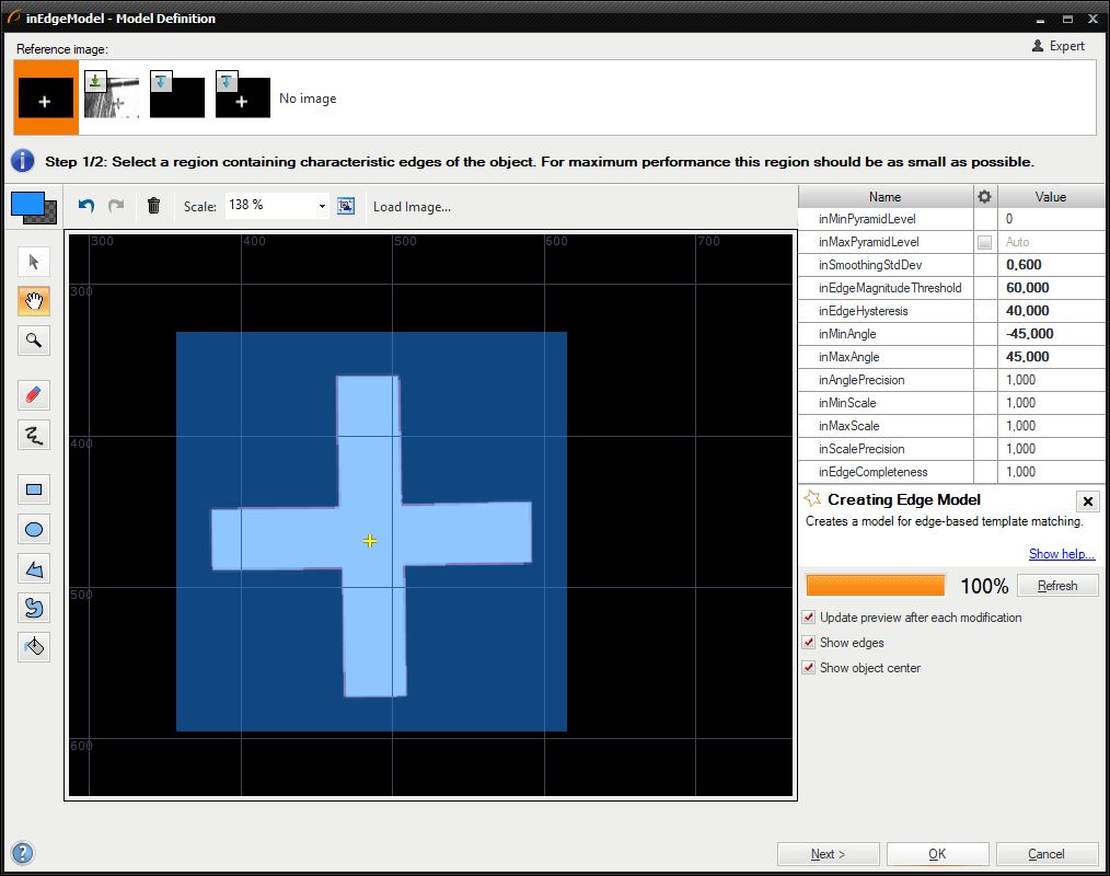
- The angle parameters allow detection of rotated markers. Setting them to -45 and 45 degrees will result in creating models for every rotation in the 90-degree range. Since the marker is symmetrical horizontally and vertically this range is more than enough. The range may be set to a greater number, however this would slow down the execution time without noticeable accuracy improvement.
- Mark the area of the marker and set the parameters like it is shown in the following image.
- To ensure fast and robust execution you can change appropriate parameters in the filter properties set the parameters.
- Changing the inMinPyramidLevel to 1 speeds up the execution since the required accuracy is lower.
- Set the inEdgeThreshold to 8 so that weaker edges can be detected.
- Set the inEdgePolarityMode to Ignore. This means that the system will seek both object darker than the background and brighter.
- Finally, enter 0.680 into the inMinScore parameter to detect objects which are partially obscured.
- Since the training image is not needed during normal operation you can disable both the EmptyImage and the DrawPaths_SingleColor filters to speed up the execution.
マクロフィルタ メイン
使用したフィルタ
| アイコン | 名前 | 説明 |
|---|---|---|
| LocateSingleObject_Edges1 | 輪郭がシャープで硬い物体の検出。 多くの場合、プログラムの最初のフィルターの 1 つです。 |
その他の資料
- テンプレートマッチング - テンプレート マッチング テクニックの最も詳細な説明をしています。

