
Aurora Visio Studio TOP » Program Examples » Rubber Ring
Rubber Ring
目的
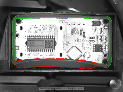
The aim of the program is to detect improperly assembled segments of a rubber band.
Input
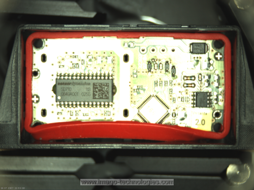
An image of a chip with an assembled rubber band around it.
Output
Proper and improper segments of the rubber band.
ヒント
It is possible to achieve this goal in many ways. In this solution we will use Blob Analysis as it is one of the easiest approach.
接続のラベル付けについては こちらを参照ください。
Solution (AVS)
- In Workspace Explorer open workspace Examples and in Film strip window select RubberRing dataset. Drag the Image channel to the ACQUIRE section.
- Add the ThresholdToRegion_HSx and connect the ReadFilmstrip output with the inRgbImage.
- Click on the ThresholdToRegion_HSx filter and make these changes in the Properties window (in the left bottom corner):
- Set the inEndHue to 10.
- Set the inMinSaturation to 190.
- Set the inMaxSaturation to 255.
- Set the inMinBrightness to 65.
- Set the inMaxBrightness to 255.
The values above were chosen based on information from the diagHSxImage diagnostic output which displays HSV values. Using the color-picker tool you should easily get these values as well. Please note that they are prompted as RGB values, but they are HSV values in fact.
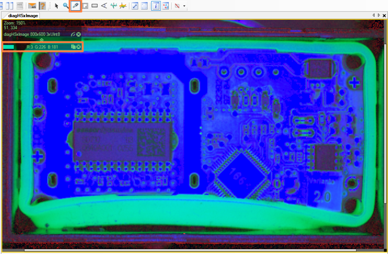
HSV values obtained with a color-picker tool.
- Add the CloseRegion filter to close the region corresponding to the rubber ring. Connect the outRegion from a previous filter with the inRegion of the current one.
- Click on the CloseRegion filter. In the Properties window:
- Add the FillRegionHoles filter to fill the holes in the region. Connect the outRegion to the inRegion.
- Click on the FillRegionHoles filter and in Properties window set the inMaxHoleArea to 10000 to avoid filling the area inside the rubber ring.
- Add the OpenRegion filter to find the bolder area of the rubber ring. Connect the outRegion to the inRegion.
- Click on the OpenRegion filter. In the Properties window:
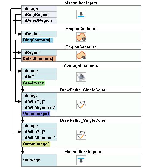
- Now add a new step macrofilter, name it DrawDefects and add following inputs to it:
- the ReadFilmstrip output and name it inImage.
- the outRegion and name it inRingRegion.
- the outRegion and name it inErrors.
- Get inside newly-created macrofilter and add the RegionContours filter.
- Connect the inRingRegion with the inRegion. Click on the RegionContours filter and set the inContourMode to PixelEdges.
- Add another RegionContours filter to get an array of closed paths corresponding to the contours of the input region and connect inErrors to its inRegion input. Set the inContourMode to PixelEdges.
- Add the AverageChannels filter to get a grayscale image and connect macrofilter's inImage to the inImage.
- Add the DrawPaths_SingleColor filter.
- Connect the outImage to the inImage.
- Connect the outContours from the first RegionContours filter and connect to the inPaths.
- Click on the DrawPaths_SingleColor and in Properties window make these changes:
- Set the inColor to green.
- Set the inDrawingStyle.Opacity to 0.75.
- Set the inDrawingStyle.Thickness to 2.
- Set the inDrawingStyle.PointSize to 2.
- Add another DrawPaths_SingleColor filter.
- Connect the outImage from a previous filter with the inImage of the current one.
- Connect the outContours from the other RegionContours filter and connect to the inPaths.
- Click on the DrawPaths_SingleColor filter and in Properties window make these changes:
- Set the inColor to red.
- Set the inDrawingStyle.Thickness to 3.
- Set the inDrawingStyle.PointSize to 2.
- Connect the outImage to macrofilter outputs and name it outImage.
マクロフィルタ メイン
Macrofilter DrawDefects
使用したフィルタ
| アイコン | 名前 | 説明 |
|---|---|---|
| ThresholdToRegion_HSx | Extraction of a region characterized with a specific color. | |
| AverageChannels | Creates a monochromatic image by averaging the input image channels. | |
| RegionContours | Computes an array of closed paths corresponding to the contours of the input region. | |
| DrawPaths_SingleColor | Draws paths on an image with a single color. | |
| FillRegionHoles | 入力領域にピクセルを追加し、穴がないようにします。 | |
| CloseRegion | Filling-in small gaps in a region without making it thicker. | |
| OpenRegion | Removing small parts from a region without making it thinner. |
その他の資料
- ブロブ解析 - ブロブ分析手法について詳しく説明します。