Aurora Visio Studio TOP »
Program Examples »
Fourier Analysis
Fourier Analysis
目的
The aim of the application is to present the Fourier analysis of a sample image and to show how periodic disturbances impact on the image.
The Fourier transform helps with more compact encoding images, making visible image features unobservable in the spatial domain (such as periodic interference), designing image filters in the frequency domain and implementation of high-speed image filtering methods.
Input
The Lena image from the TestImage filter.

Output
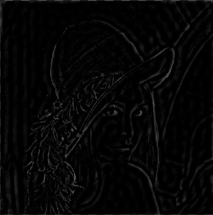
The image after Fourier transformations.
Solution (AVS)
>> ここをクリックしてソリューションを開く
>> ここをクリックしてソリューションを非表示にする
-
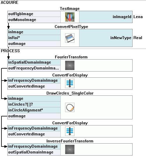
Add the TestImage filter to the Acquire section. Choose Lena in the Parameters.
-
Add the ConvertPixelType filter and set the inNewType as Real to prepare data for the Fourier transform. Connect its inImage input with the outMonoImage output.
-
Add the FourierTransform filter to transform the image into the frequency domain. Connect its inSpatialDomainImage input with the ConvertPixelType output.
-
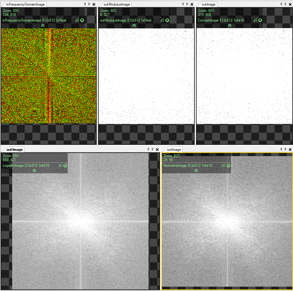
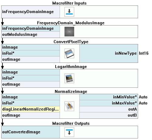
Now we need to convert the frequency domain into the image Fourier spectrum:
-
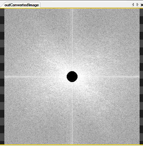
Return to the Main macrofilter. To see how periodic disturbances impact on the image, modify the spectrum:
- Add the DrawCircles_SingleColor filter and connect its input with the ConvertForDisplay output.
- Add a new item to the inCircles in the Parameters section. Set its Center to {256,256} and the Radius to 20.
- Drag the ConvertForDisplay macrofilter from the Project Explorer section under the DrawCircles_SingleColor to add another instance of this Step. Connect its input with the DrawArcs_SingleColor output. Show the new spectrum on a new preview window.
- Add the InverseFourierTransform filter to show the results of the spectrum modification. Connect its input to the DrawArcs_SingleColor output. Show the results on a new preview window.
マクロフィルタ メイン
Macrofilter ConvertForDisplay
使用したフィルタ
>> ここをクリックしてフィルタリストを開く
>> ここをクリックしてフィルタリストを閉じる
| アイコン |
名前 |
説明 |
 |
LogarithmImage |
Transforms an image in such a way that a quotient on the input image becomes a difference on the output image. This can be useful for dealing with variable illumination. |
 |
DrawCircles_SingleColor |
単一の色で画像上に円を描画します。 |
 |
InverseFourierTransform |
Transforms an image in frequency domain back to spatial domain using inverse Fourier transformation. |
 |
TestImage |
Makes it possible to quickly present results of various image processing filters. |
 |
ConvertPixelType |
Changes the type of pixel components. |
 |
FrequencyDomain_ModulusImage |
Computes the modulus of each frequency domain image pixel. |
 |
NormalizeImage |
Aims at better using the image's dynamic range to represent an interesting subset of pixel values. |
 |
FourierTransform |
Transforms an image into frequency domain using Fourier transformation. |


